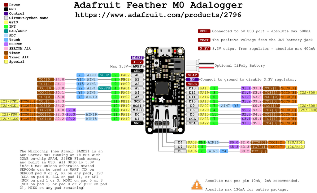
The Adafruit Feather has a SAMD Arm M0 SoC. In the Arduino IDE I installed
the Arduino SAMD board file and use the Arduino Zero (USB).
Feather Logger
Pins
#0 / RX - GPIO #0, also receive (input) pin for Serial1 (hardware UART), also can be analog input
#1 / TX - GPIO #1, also transmit (output) pin for Serial1, also can be analog input
#20 / SDA - GPIO #20, also the I2C (Wire) data pin. There's no pull up on this pin by default so when using with I2C, you may need a 2.2K-10K pullup.
#21 / SCL - GPIO #21, also the I2C (Wire) clock pin. There's no pull up on this pin by default so when using with I2C, you may need a 2.2K-10K pullup.
#5 - GPIO #5
#6 - GPIO #6
#9 - GPIO #9, also analog input A7. This analog input is connected to a voltage divider for the lipoly battery so be aware that this pin naturally 'sits' at around 2VDC due to the resistor divider
#10 - GPIO #10
#11 - GPIO #11
#12 - GPIO #12
#13 - GPIO #13 and is connected to the red LED next to the USB jack
SCK/MOSI/MISO (GPIO 24/23/22)- These are the hardware SPI pins, you can use them as everyday GPIO pins (but recommend keeping them free as they are best used for hardware SPI connections for high speed.
A0 - This pin is analog input A0 but is also an analog output due to having a DAC (digital-to-analog converter). You can set the raw voltage to anything from 0 to 3.3V, unlike PWM outputs this is a true analog output
A1 thru A5 - These are each analog input as well as digital I/O pins.
SD Card
#4 - used as the MicroSD card CS (chip select) pin
#7 - used as the MicroSD card CD (card detect) pin. If you want to detect when a card is inserted/removed, configure this pin as an input with a pullup. When the pin reads low (0V) then there is no card inserted. When the pin reads high, then a card is in place. It will not tell you if the card is valid, its just a mechanical switch
#8 - Tied to a green LED, next to the SD card. It might be handy to blink this LED when writing / reading valid data